Computing odometry for wheeled mobile robots
In the realm of mobile robotics, accurate estimation of a robot’s position and orientation is crucial for successful navigation and control. One common technique used to achieve this is computing odometry. Odometry is the process of estimating a robot’s position and orientation (or, jointly known as pose) by analyzing the wheel movements and rotations. In this article, we will focus primarily on mobile robots and this article builds on prior knowledge of coordinate transformations which will be used to deduce updated robot poses as it explores the environment.
Understanding odometry
Odometry (also known as dead-reckoning) is based on the principle that the distance a wheeled robot travels can be determined by measuring the rotation of its wheels. By measuring the rotational movement of each wheel and applying kinematic equations, it is possible to estimate the robot’s change in position and orientation. Odometry is crucial for precise robot navigation, especially in scenarios where external positioning systems like GPS are unavailable.
Tools for computing odometry
To compute odometry, the robot is equipped with wheel encoders, which are sensors that record the rotation of each wheel. These encoders provide precise measurements of the wheel rotations, allowing for accurate estimation of the robot’s movement.
There are several types of wheel encoders commonly used in robotics:
1. Optical Encoders:
Incremental Optical Encoders: These encoders generate pulses as the wheel rotates. They provide information on the direction and speed of the wheel’s rotation.
Absolute Optical Encoders: These encoders produce a unique digital code for each position. This allows the robot to instantly determine its wheel’s absolute position, even if it was powered off or moved while off.
2. Magnetic Encoders:
Rotary Magnetic Encoders: These encoders use a rotating magnet and a sensor to detect changes in the magnetic field as the wheel turns. They provide information on the wheel’s rotation and direction.
Linear Magnetic Encoders: Linear magnetic encoders are used to measure linear motion, such as a robot’s linear position on a track or rail.
3. Capacitive Encoders:
Capacitive encoders use changes in capacitance to measure movement. They are often used in applications requiring high precision and reliability.
4. Inductive Encoders:
Inductive encoders employ variations in inductance to measure wheel rotation. They are known for their durability and suitability for harsh environments.
5. Hall Effect Encoders:
Hall effect encoders use the Hall effect to measure changes in a magnetic field, providing information on the wheel’s position and rotation.
6. Optical Quadrature Encoders:
Optical quadrature encoders use two detectors with a quarter-phase shift to provide more accurate direction information. They are frequently used for precision control and robotics applications.
7. Incremental Encoders:
Incremental encoders produce pulse signals that indicate changes in wheel position and speed. They are often used in conjunction with other sensors for more accurate measurements.
8. Resolvers:
Resolvers are sensors that provide absolute position feedback with good accuracy and reliability. They are often used in industrial robots.
9. Rotary Encoders:
Rotary encoders are versatile and can be used in various applications. They measure the angular position of a wheel and can be either absolute or incremental.
10. Linear Encoders: – Linear encoders are used for measuring linear movement, such as linear translation stages or robotic arms.
The most common type of encoder used in robotics and automation applications is the Optical Encoder. Optical encoders are widely popular due to their accuracy, reliability, and versatility. They can provide both incremental and absolute position feedback, making them suitable for various tasks.
Here’s why optical encoders are commonly used:
1. Precision: Optical encoders can provide highly accurate feedback on position and speed, making them suitable for applications that require precise control, such as industrial robots and CNC machines.
2. Versatility: They are available in both incremental and absolute versions, allowing them to serve different requirements. Incremental optical encoders are often used for speed and direction sensing, while absolute optical encoders provide precise position feedback.
3. Durability: Optical encoders are relatively robust and can operate in a wide range of environmental conditions. Sealed or “sealed-bearing” designs are available for added protection in harsh environments.
4. Non-Contact Sensing: Optical encoders work on a non-contact sensing principle, which means they don’t wear out as quickly as encoders that use physical contact mechanisms.
5. High Resolution: They offer high resolution, allowing for precise control and motion feedback.
While optical encoders are prevalent, the choice of encoder type depends on the specific needs of a robotics or automation application. Factors such as required precision, environmental conditions, and cost can influence the selection of the appropriate encoder technology. Oftentimes, an Inertial Measurement Unit (IMU) contains accelerometers and gyroscopes to measure acceleration and angular velocity. These readings complement odometry data to improve accuracy.
Odometry computation
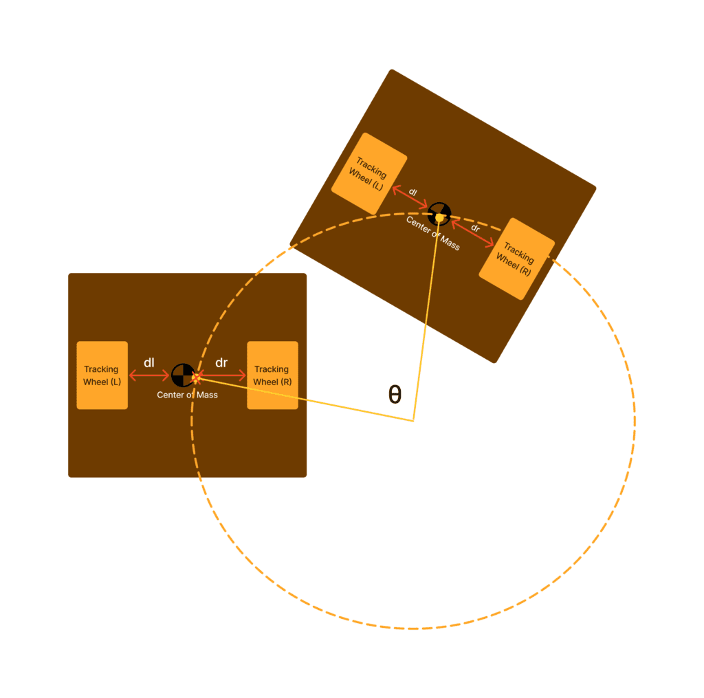
Now let us look into how encoders typically get used in computing the odometry of the wheeled mobile robot. The process of computing odometry involves several steps and may vary depending on the drive train and steering mechanisms of the robot but for a two wheeled differential drive train for example, the process looks like this:
For the change in the robot’s position (Δx, Δy) and its orientation (Δθ) after traveling a distance on the left (dl) and right (dr) wheels:
Δx=12⋅(dr+dl)⋅cos(θ)
Δy=12⋅(dr+dl)⋅sin(θ)
Δθ=1w⋅(dr–dl)
Where:
Δθ
is the current orientation of the robot.w=dr+dl
is the distance between the wheels.
Challenges & limitations
While odometry is a valuable method for estimating a wheeled mobile robot’s position and orientation, it’s essential to be aware of its inherent challenges and limitations. These factors can affect the accuracy of odometry-based localization and navigation.
Wheel Slip: Wheel slip occurs when the wheels of the robot lose traction with the ground. This can happen due to uneven terrain, slippery surfaces, or sudden movements. Odometry relies on the assumption that the wheels move without slip, making it less accurate in such situations.
Wheel Wear: As a robot’s wheels wear out over time, the circumference may change slightly. This change can significantly impact odometry calculations, leading to cumulative errors in position estimation.
Nonholonomic Constraints: Odometry assumes that a robot moves holonomically, meaning it can move in any direction without constraints. However, many wheeled robots have nonholonomic constraints, meaning they cannot move in all directions freely. This can result in discrepancies between the estimated and actual positions.
Sensor Noise: Odometry is highly sensitive to sensor noise, especially in low-cost wheeled robots. Any noise in the wheel encoders or sensors used for distance and rotation measurements can introduce errors into the odometry calculations.
Accumulative Errors: Odometry-based estimates are prone to cumulative errors. As the robot moves, small errors in distance and angle measurements accumulate over time, leading to significant discrepancies in position and orientation.
Lack of Global Information: Odometry provides a relative estimate of robot motion but does not consider global information or external landmarks. This makes it challenging for the robot to correct its position if it drifts over time.
External Disturbances: External factors such as bumps, vibrations, or pushes can disrupt odometry calculations. These disturbances may lead to temporary deviations in position estimates.
Calibration Requirements: Maintaining accurate odometry often requires regular calibration of sensors and wheels. This calibration process can be time-consuming and may need technical expertise.
Computational Load: Real-time odometry calculations can be computationally intensive, depending on the complexity of the robot’s movements and sensor setup. This load can limit the robot’s ability to perform other tasks efficiently.
Integration with Other Localization Methods: In practice, odometry is often used in conjunction with other localization methods like GPS or visual odometry to improve accuracy. Integrating multiple sensors and algorithms can be complex and require synchronization.
Despite these challenges, odometry remains a valuable tool for robotics, especially for short-term, indoor applications. Overcoming these limitations often involves using complementary sensor data, advanced filtering techniques, and considering the specific operational environment to enhance odometry’s performance.
Key takeaways
In summary, odometry plays a crucial role in estimating the position and orientation of wheeled mobile robots. By analyzing the wheel rotations and applying kinematic equations, odometry calculations provide valuable information for navigation and control. Despite its limitations, odometry remains a fundamental technique in robotics, enabling robots to perceive and interact with their environment.