Mastering coordinate systems and frame relations
Coordinate systems are crucial for representing and defining positions, orientations, and transformations in various fields, including robotics, computer graphics, and engineering. These systems provide a reference frame, allowing us to describe the location and orientation of objects in a structured manner, usually with respect to a map. In mobile robotics, unless a robot knows where it is (localization) and where it needs to go, it cannot really plan the navigation and execute the path. To be able to do all this, it needs to understand the scene with respect to a frame of reference provided by a coordinate system.
There are various types of coordinate systems, such as Cartesian, polar, cylindrical, and spherical. Each has its unique characteristics, making them suitable for specific applications. Understanding these coordinate systems is fundamental for relating different coordinate frames together.
In this comprehensive guide, we delve into the intricate world of coordinate systems and the essential methods to relate multiple coordinate frames together.
Types of Coordinate systems
In the world of robotics, accurate representation of positions and orientations is crucial for effective operation and control. Various coordinate systems provide distinct ways of describing spatial relationships. Let’s explore some of the most commonly used coordinate systems and understand when to use each one:
1. Cartesian Coordinate System
The Cartesian coordinate system, also known as rectangular coordinates, is the most widely used coordinate system in robotics. It employs three orthogonal axes (x, y, and z) to define a point’s position in 3D space. This system is ideal for tasks that require precise positional accuracy, such as robotic arm control and path planning.
2. Polar Coordinate System
The polar coordinate system utilizes two values, namely radial distance $$(r)$$ and azimuth angle $$(\theta)$$, to locate a point relative to a reference origin. Polar coordinates are well-suited for applications involving circular movements, such as robotic arms with rotating joints or tasks that involve radial symmetry.
3. Cylindrical Coordinate System
The cylindrical coordinate system is an extension of the polar system. It incorporates an additional vertical axis $$(z)$$ to define points in 3D space. Cylindrical coordinates are commonly used in robotics for tasks involving rotational and vertical movements, such as robotic manipulators working in cylindrical workspaces.
4. Spherical Coordinate System
The spherical coordinate system uses three values: radial distance $$(r)$$, polar angle $$(\theta)$$, and azimuth angle $$(\phi)$$, to specify a point’s location in 3D space. This system is particularly useful for tasks involving spherical symmetry or applications where orientation relative to a reference point is critical.
Selecting the right Coordinate system
The choice of coordinate system depends on the specific requirements of a robotic application. Consider the following factors when selecting the appropriate system:
Task Nature: Identify the predominant type of movements involved in your application – linear, circular, or spherical.
Simplicity: Choose a coordinate system that simplifies the mathematical representation of your robotic tasks.
Consistency: Ensure consistency with existing coordinate systems used in your robotic system or environment.
Ease of Transformation: Opt for a system that facilitates easy transformation between different coordinate frames.
Significance of relating multiple Coordinate frames
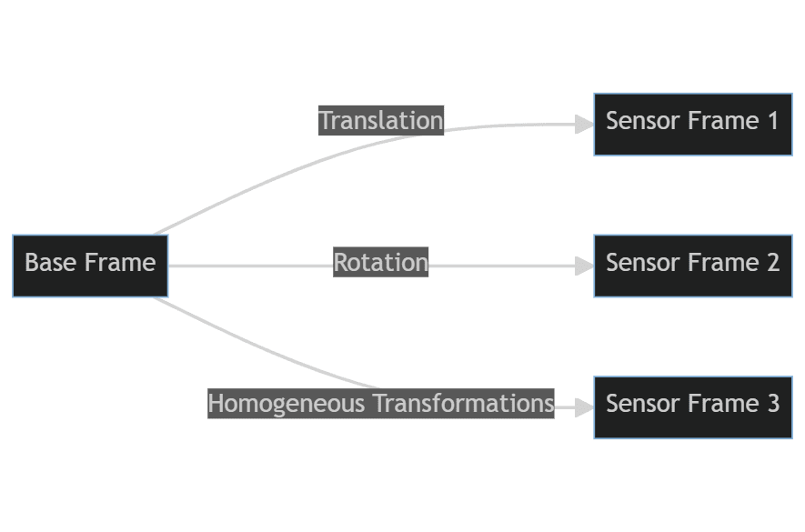
In many real-world scenarios, it’s essential to relate multiple coordinate frames to achieve accurate and consistent data representation. For instance, in robotics, a robot may have sensors with their own coordinate frames, and understanding how they relate to the robot’s base frame is crucial for navigation and manipulation tasks.
Additionally, in computer graphics, artists often work with multiple coordinate systems when creating 3D models and animations. Relating these coordinate frames allows seamless integration and proper rendering of complex scenes.
Methods to relate multiple Coordinate frames
To relate multiple coordinate frames, several mathematical techniques and transformations come into play. Here are some of the key methods:
1. Translation
Translation is the simplest way to relate two coordinate frames. It involves shifting one frame’s origin to align with another frame’s origin. By specifying the displacement vector, we can express points in one frame with respect to the other.
2. Rotation
Rotation allows us to change the orientation of one frame with respect to another. We use rotation matrices or quaternions to represent the rotational transformations. This method is commonly used in computer graphics and robotics to align objects correctly.
3. Homogeneous Transformations
Homogeneous transformations combine translation and rotation in a single matrix. These transformations are particularly powerful as they enable us to express complex spatial relationships between coordinate frames in one concise form.
Coordinate systems and frame relations in Robotics
Coordinate systems and frame relations play a pivotal role in the field of robotics, enabling precise control and operation of robotic systems. Let’s explore some practical applications where understanding these concepts is vital:
1. Simultaneous Localization and Mapping (SLAM)
SLAM is a crucial capability for autonomous robots and drones. By integrating sensor data from cameras, lidars, and other sensors, robots can map their surroundings and simultaneously estimate their own position within that map. Properly relating sensor data to the robot’s base frame is vital for accurate localization and reliable mapping.
2. Object Recognition and detection
For robots to interact with their environment effectively, they must recognize objects and their relative location and orientation. Using coordinate systems, robots can detect and identify objects in their vicinity.
3. Mobile robot navigation
Mobile robots, such as unmanned ground and aerial vehicles, rely on coordinate systems to navigate safely and efficiently. By employing transformations like translation and rotation, mobile robots can accurately perceive their position relative to a map and plan collision-free paths to reach their destination.
4. Robotic Visual Servoing
Visual servoing is a technique that uses visual feedback to control the motion of a robot. By relating the robot’s camera frame to the world frame, robots can track and follow objects, execute pick-and-place tasks, or maintain a desired pose relative to the target.
5. Collaborative Robotics (Cobots)
In collaborative robotics, where robots work alongside humans, coordinate systems ensure safe and seamless collaboration. By defining a shared coordinate frame between the robot and human workspace, the robot can adapt its movements to accommodate human presence and avoid potential collisions.
6. Industrial Automation
Coordinate systems are widely used in industrial automation for tasks like material handling. Similar to mobile robot navigation, industrial robots in warehouses need to infer their own position and orientation, that of their peers and then safely navigate to the goal to ferry packages and materials thereby helping with industrial automation.
7. Robot Calibration and Error Compensation
Robotic systems are susceptible to errors due to mechanical imperfections and sensor inaccuracies. Calibration of the robot’s kinematic model using coordinate systems helps in error compensation, improving the overall system accuracy.
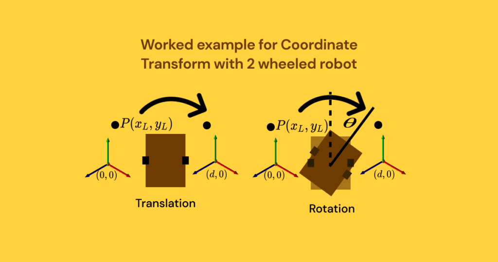
Worked example of Coordinate transforms for a wheeled mobile robot
Imagine we have a wheeled mobile robot, and we want to transform a point from the coordinate frame of the left wheel base to the coordinate frame of the right wheel base.
Let’s assume that the left wheel base’s coordinate system is denoted by “L” with origin (0, 0), and the right wheel base’s coordinate system is denoted by “R” with origin (d, 0), where “d” represents the distance between the two wheel bases.
Let’s consider a point P in the left wheel base coordinate system, represented as $$(x_L, y_L)$$.
To transform this point to the right wheel base coordinate system, we need to apply a translation along the x-axis by the distance “d”.
The transformation can be expressed using the following equations:
$$
x_R = x_L + d \\
y_R = y_L
$$
In this transformation, we are simply adding the distance “d” to the x-coordinate of the point in the left wheel base to obtain the corresponding x-coordinate in the right wheel base. The y-coordinate remains unchanged since there is no movement along the y-axis during this transformation.
Let’s enhance the example to include rotation as well. Assume that in addition to the translation, the robot undergoes a rotation with an angle $$\theta$$ from the left wheel base coordinate system (L) to the right wheel base coordinate system (R). The rotation is performed around the origin of the left wheel base coordinate system.
To transform the point $$P(x_L, y_L)$$ from the left wheel base to the right wheel base, we need to apply both translation and rotation. The transformed coordinates $$(x_R, y_R)$$ can be calculated as follows:
$$x_R = x_L*cos(θ) – y_L*sin(θ) + d\\
y_R = x_L*sin(θ) + y_L*cos(θ)$$
Let’s perform the same transformation using homogeneous transforms and demonstrate how they simplify the computation by combining all the translation and rotation operations into a single matrix.
The homogeneous transformation matrix for a 2D transformation combining translation and rotation can be represented as follows:
\[
\begin{bmatrix}
x_R \\
y_R \\
1
\end{bmatrix}
=
\begin{bmatrix}
\cos(\theta) & -\sin(\theta) & dx \\
\sin(\theta) & \cos(\theta) & dy \\
0 & 0 & 1
\end{bmatrix}
\begin{bmatrix}
x_L \\
y_L \\
1
\end{bmatrix}
\]
As you can see, homogeneous transforms allowed us to combine all the translation and rotation computations into a single matrix multiplication, making the transformation process more efficient and straightforward. This is especially beneficial when dealing with complex transformations and multiple points, as it simplifies the calculations and improves the overall computational efficiency.
Key takeaways
In conclusion, mastering coordinate systems and their interrelations is essential for various industries and applications. We have explored the basics of coordinate systems, the significance of relating multiple frames, and the methods to achieve accurate transformations.
By applying this knowledge effectively, you can optimize robotic systems, create stunning computer graphics, analyze spatial data in GIS, and enhance virtual and augmented reality experiences. Embrace the power of coordinate systems, and unlock a world of possibilities for your projects and endeavors.